
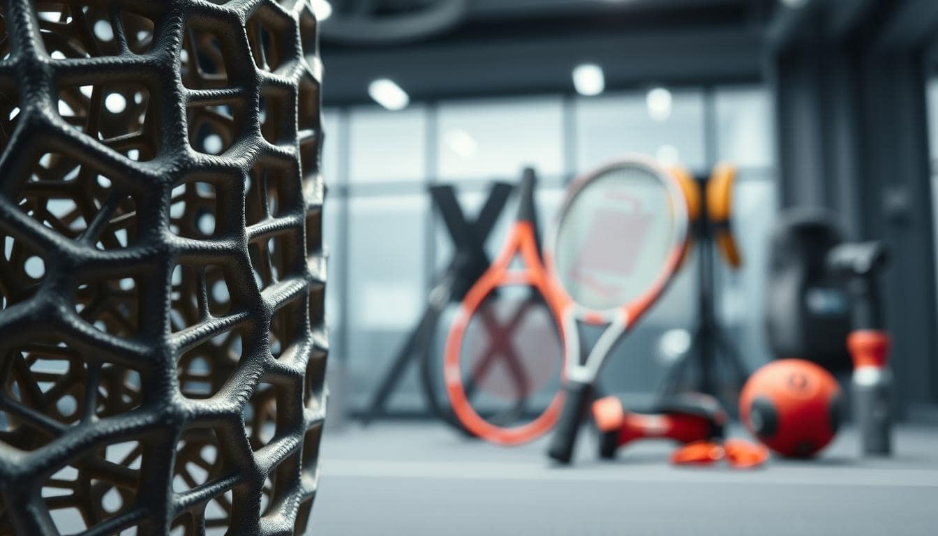
Remember wooden tennis rackets and waterlogged leather footballs? Those days were tough. Now, the game has changed at the molecular level.
We’ve moved from carving wood to programming polymers. Today’s gear is engineered atom by atom. It starts in a CAD model, not a factory. Engineers test a digital twin of a shoe’s midsole or a bike’s frame before using any material.
This digital-first approach allows for radical experimentation. The most thrilling frontier? Auxetic lattices. Unlike conventional materials, auxetic structures get wider when stretched. This means gear that can absorb impact and return to its original shape with eerie, almost intelligent, resilience.
This isn’t just a new material; it’s a new material philosophy. We’re not just making a better mousetrap. We’re writing the genetic code for the equipment itself. The auxetic lattices and bio-based foams of tomorrow are being prototyped in a virtual world. Yesterday’s high-tech gear looks like a relic from the Stone Age.
Before You Innovate, You Must Define the Box
Every great innovation in sports equipment starts with a simple question: “What is this thing actually for?” This question helps us tell the difference between a gimmick and something truly groundbreaking. Before we can think outside the box, we need to know the rules. This is the hard work of defining the problem.
It’s not about finding the answer right away. It’s about asking the right question with great precision. This is like being a neurosurgeon with words.
Let’s forget about the flashy design for now. Before we can make a bike helmet lighter, we need to understand what it will go through. It’s not just about making it strong. We need to know the loads it will face, like a 1.5-meter drop test.
We also need to think about the boundary conditions, like extreme temperatures. And we must consider the safety factors to ensure the helmet can handle the worst-case scenario of a crash.
This is where dreams meet reality. You might want a tennis racket that’s light and stiff, but physics has other plans. The constraints help us be creative. They make us think about how to use materials better.
For example, advanced polymer foams like E-TPU are designed to absorb energy. They work within specific temperature and impact ranges. Engineers don’t just pick E-TPU. They define the problem it needs to solve.
This isn’t just about building something that works. It’s about creating something amazing. We need to define the problem with great detail. Only then can we come up with innovative solutions.
Generative Workflows: Where the Algorithm Takes the Pencil
Forget everything you know about design. Today, designers work with algorithms, not just pencils. These algorithms solve engineering problems like physics puzzles. This is generative design, where we define the problem and let the algorithm find solutions we can’t imagine.
This method, combining topology, lattice, and thickness optimization, changes designs from the ground up. We don’t just tweak designs; we start from scratch. The software dreams up solutions that look like they’re from another world.
Think of it as a digital survival of the fittest. The algorithm creates many designs, testing them against our needs. The best designs survive and mix, creating new, optimal forms.
The Three Pillars of Algorithmic Form-Finding
Generative design uses a variety of methods, each with its own strengths. The table below shows the main methods, but think of them as a combined arsenal, not an either-or choice.
| Method | What it Does | Best For | Ideal Material Context | Real-World Analogy |
|---|---|---|---|---|
| Topology Optimization | Carves away non-essential material from a design space, leaving only the “skeleton” of a part that carries the load. | Lightweighting primary structural components (bike frames, brackets, engine mounts). | High-performance metals, composites. | A sculptor removing marble to reveal the statue within. |
| Lattice Optimization | Generates complex internal or external lattice structures that balance strength, weight, and energy absorption. | Mid-soles, padding, energy-absorbing structures, lightweight cores. | Thermoplastic composites for 3D printing. | The intricately lightweight interior of a bird’s bone. |
| Thickness Optimization | Algorithmically varies the wall thickness of a part to add material only where it’s needed for structural integrity. | Thin-walled structures, pressure vessels, casings, fluid channels. | Metals, polymers, and thermoplastic composites. | Varying the thickness of a bridge’s I-beam along its length. |
From Algorithm to Artifact: The Workflow in Action
Imagine designing a new bicycle crank arm. In the old days, we’d start with a block of aluminum and a CAD model. Now, we start with physics. We define the “keep-out” zones, loads, and goals, and let the algorithm dream up a design.
The algorithm might suggest a design that looks like a cybernetic cheetah’s femur—a beautiful, organic webbing of material. But we can’t machine that. So we move to the lattice optimization stage, where the algorithm fills the interior with a mathematically perfect lattice, creating a part that is 40% lighter and stronger than the original block. This is where materials like advanced thermoplastic composites shine—they can be 3D printed into these forms that would be impossible to machine or mold.
The Material is the Message
This is where the magic of modern materials meets the algorithm. The bizarre, organic forms that generative design creates are often only manufacturable through additive manufacturing. And this is the killer app for thermoplastic composites. These materials, with their high strength-to-weight ratio and ability to be 3D printed into mind-bending geometries, are the perfect partners for generative design. The algorithm isn’t limited by the constraints of traditional manufacturing; it’s free to propose the most efficient structure, and the printer is free to build it.
The software doesn’t care about aesthetics; it cares about physics. It will happily design a part that looks like the ribcage of a dragon if it’s the most efficient load path. Our job as engineers is to provide the guardrails—the loads, the constraints, the manufacturing limits. The algorithm’s job is to find the form. The result is a collaboration: human intuition setting the problem, artificial intelligence exploring the solution space, and advanced materials like thermoplastic composites making the impossible design not just possible, but printable.
In the end, generative design isn’t about replacing the designer. It’s about expanding the realm of the possible. It asks a simple, profound question: “If you could start over, with no preconceptions, what would the perfect part look like?” The answer is often as beautiful as it is efficient.
CAE Validation: The Digital Proving Grounds
You’ve got a strange, beautiful part on your screen. It looks like something from a sci-fi movie. The generative algorithm is like an artist, but is it an engineer? That’s where the real work starts.
Welcome to CAE validation, where we check if the part works. We stop admiring the design and start testing it.
This phase is like a digital wind tunnel. We test the design in many ways. We check if it’s strong enough and if it works as planned.

Mesh Strategy: The Devil in the (Tiny) Details
Meshing is like translating your 3D model into a language the solver can understand. A coarse mesh is like a low-resolution photo. A fine mesh is like a high-resolution image.
Our strategy is to use a fine mesh in critical areas and a coarser mesh elsewhere. This selective meshing gives us the accuracy we need without needing a supercomputer.
Beyond “Strong” and “Flexible”: The Material Model
Calling a material “strong” or “flexible” in CAE is not enough. We need to understand its properties fully.
We define materials by their stress-strain curves, not just a “strength” value. For example, a running shoe’s midsole foam needs its viscoelastic damping properties. This tells us how it absorbs and dissipates energy.
The Pursuit of Convergence
Convergence is the ultimate goal of CAE. We don’t just run the simulation once. We refine the mesh and run it again.
We watch the numbers. If the results keep changing, the solution hasn’t converged. We refine and re-run until the results stabilize. That’s convergence.
This isn’t just a box-ticking exercise. A non-converged result is a guess. A converged result is a prediction. In high-performance sports gear, a guess isn’t good enough. We need to be sure the part will behave as predicted.
Multiphysics Considerations (Impact, Airflow, Acoustics, Thermal)
Multiphysics simulation is like a full IMAX 3D experience of a product’s performance. In the real world, forces don’t work alone. Your gear faces a mix of physics—impact, heat, airflow, and noise—all at once.
Designing for this reality means solving more than one problem at a time. It’s about making sure a motocross boot vents heat while protecting the shin. Or a racing helmet can deflect a 200mph windblast and keep the driver cool.
Bio-based resins and other advanced polymers are more than eco-credentials. Their material properties, like specific damping coefficients and thermal conductivity, play a key role in simulations. You’re not just modeling a helmet’s crush resistance; you’re modeling how its unique composite layup manages thermal load and acoustic resonance.
From Single Physics to Symphony
Consider a downhill ski. A static load analysis ensures it doesn’t snap. But multiphysics asks: How does its camber and flex pattern affect the turbulent airflow over its surface at 70 mph? Does that airflow create a harmonic vibration (an acoustic signature) that chatters at a specific speed?
A uniphysics model sees a static beam. A multiphysics model sees a dynamic airfoil in a fluid-structure interaction, where vibration (acoustics) can affect material fatigue.
This is the core of modern sports engineering. It’s not just about if something breaks, but how it performs, breathes, and even sounds under a full-spectrum assault of real-world physics.
The Four-Forces Framework
Modern simulation software lets us stage a physics mosh pit. Here’s what that mosh pit typically includes:
- Structural-Acoustic Coupling: How a tennis racket’s frame geometry and string tension interact to create a specific, desirable “ping” and feel.
- Fluid-Structure Interaction (FSI): How a cyclist’s aero helmet deforms minutely under 200 km/h winds, altering its drag profile in real-time.
- Thermo-Mechanical Analysis: How the heat from an athlete’s foot in a motocross boot interacts with the material’s thermal expansion and moisture-wicking liners.
- Shock & Vibration: How a composite bike frame absorbs road buzz (high-frequency, low-amplitude) differently than a pothole impact (low-frequency, high-amplitude).
For instance, the energy absorption of a helmet liner isn’t just about a single hit. It’s about how the bio-based resins and auxetic foams in the liner manage the impact energy while also considering the heat buildup on the rider’s head and the aerodynamic noise at speed. One force doesn’t stop for another.
The Real-World Payoff
This isn’t academic. A Formula 1 team uses multiphysics to ensure a helmet visor can withstand a pebble strike without shattering (impact), manage driver cooling (thermal), and minimize wind noise (acoustics) and drag (fluid dynamics). It’s one component, but it must pass a gauntlet of simultaneous, conflicting demands.
This holistic approach is where sustainable materials shine. The specific damping and thermal properties of new bio-based resins can be precisely modeled to see how they perform not just in a drop test, but in the complex, multi-variable reality of a world that is anything but a sterile lab.
Digital Twins & Test Correlation: The Feedback Loop That Actually Listens
Forget the static CAD model gathering digital dust in some server folder. A digital twin isn’t a one-and-done 3D file; it’s a living, breathing, data-gobbling doppelgänger of its physical counterpart. This is where your design stops being a hypothesis and starts having a two-way conversation with reality.
Think of it as a fitness tracker for your product. Strapped with sensors, the physical prototype is no longer a silent object. It whispers its secrets—strain, temperature, vibration, impact forces—back to its digital twin in the cloud. This isn’t just telemetry; it’s a continuous performance review. Did that auxetic lattice we designed actually absorb the predicted 15% more energy on impact? The sensor feedback flowing into the digital twin gives you the unvarnished truth, not the simulation’s best guess.
This is where the magic of model updating happens. That initial digital model, based on material properties and physics, was a best guess. The real-world data from the sensors acts like a masterclass in reality. The twin learns, adapts, and its virtual model is refined. The stiffness matrix is tweaked, the fatigue model is calibrated, and the next simulation run is exponentially more accurate. It’s a self-improving loop: build, test with sensors, feed data to the twin, refine the model, repeat.
This feedback loop is the secret sauce for innovation, and it has a surprising ally: recyclability. When you know exactly how a material performs in the wild—its stress points, its failure modes, its fatigue life—you can make it do more with less. You can design for disassembly from the start, knowing precisely how components interact. This data-driven precision means you can select materials not just for performance, but for their end-of-life journey, making the product more recyclable.
The conversation isn’t one-way. As studies on material behavior, like those examining auxetic structures, validate these models, the digital twin evolves. It’s no longer just a design tool; it’s a living document of a product’s life. This closed-loop system transforms the design process from a linear sprint into a continuous, data-driven cycle of improvement, where every physical test makes the virtual world more real, and every virtual tweak makes the physical product smarter, more efficient, and, yes, more sustainable.
Prototyping & DfAM: From Digital Blueprint to Physical Part
After all the digital work, it’s time to build the thing. We take our virtual design and see if it works in real life. Additive Manufacturing (AM) is key for complex designs to go from digital to real.
But, you can’t just print anything. That’s where Design for Additive Manufacturing (DfAM) comes in. It’s not just a buzzword; it’s how we make our designs real.

DfAM is more than rules; it’s a way of thinking for AM. It’s about designing anything but only making what you can. This is where magic turns a digital dream into a real, strong part.
Choosing the right print orientation is your first big DfAM decision. It’s not just about fitting on the build plate. It’s a strategic choice that affects part strength and more.
- Strength & Anisotropy: Parts printed flat have different strengths in different directions. The right orientation can make a big difference in strength.
- Surface Finish & Overhangs: Orientation affects surface quality. Some surfaces will be smooth, while others will be rough.
- Support Structure Hellscape: Supports are needed for overhangs. Good design can reduce the need for supports.
Then, there’s the art of support strategy. The goal is to use as few supports as possible. This is where DfAM thinking is essential.
- Self-Supporting Angles: Designing features to stay within the self-supporting angle of your material (often 45°).
- Support Placement: Placing supports only where necessary to avoid scars.
- Dissolvable Supports: Using supports that can be washed away, leaving parts perfect.
Getting the part off the build plate is the next step. Post-processing is where the real work begins. That complex lattice is just the start.
- Support Removal: The process of removing supports without damaging the part.
- Surface Finishing: Sanding, bead blasting, or chemical smoothing to get the right look.
- Heat Treatment: For metals, heat treatments to get the right properties.
This is where digital dreams become real. It’s messy but necessary. DfAM turns theory into practice, making the impossible possible.
The Real Math: When ROI Stands for Return on Innovation
Let’s get real. In the world of sports equipment design, the most valuable thing isn’t what you bet. It’s what you don’t spend. The ROI from advanced simulation and digital manufacturing isn’t just about saving money. It’s about moving fast, trying new things, and asking “what if” without worrying about costs.
We’re not just swapping materials. We’re changing how we design and make things. The real ROI is in how fast you can design and make things. You’re not just making a better shin guard; you’re saving time.
Traditionally, you design, make a prototype, test it, and then do it all again. This costs a lot of time and money. With digital tools, you can test ideas in the cloud before wasting any materials. This saves time and money.
The economics are simple. Old-school tooling for complex parts can cost tens of thousands of dollars. It locks you into one design forever. Digital tools let you try many ideas quickly and cheaply. You avoid big costs and can change your design easily.
The table below shows the big difference between old and new ways of making things.
| Metric | Traditional Design & Manufacturing | Digital-First, Additive & Generative Approach | ROI Impact |
|---|---|---|---|
| Iteration Cycle Time | Weeks to months (tooling-dependent) | Hours to days (software-driven) | Reduces time-to-market from seasons to weeks. |
| Cost of Failure | High (scrapped tooling, wasted materials) | Low (failed digital models cost compute time, not physical material) | Massively de-risks the innovation process. |
| Design Freedom | Constrained by tooling and mold design. | Constrained only by physics and imagination. | Unlocks biomimetic, latticed, or other “unmachinable” geometries. |
| Tooling & Prototyping Cost | High upfront capital for molds, jigs, and fixtures. | Near-zero for digital iteration; additive manufacturing for physical validation. | Shifts cost from CapEx (tooling) to OpEx (software/compute). |
| Iteration Velocity | Slow, linear, and sequential. | Fast, parallel, and highly adaptive. | Enables “test in silico” for hundreds of variations. |
This isn’t just about saving money. It’s about avoiding the need for expensive tools. Why spend $50,000 on a mold for a part you might change soon? The new ROI is about how fast you can try new things.
This is where material databases shine. A good material database isn’t just a list. It’s a detailed guide for choosing the right materials. It turns choosing materials into a science, not an art.
The real ROI isn’t just about saving money. It’s about being ahead of the game. It’s about making custom equipment fast, not slow. You’re not just saving money. You’re gaining time and options.
Case Study: Optimizing a Protective Component
Let’s dive into a real-world challenge. Our goal is to create a next-generation knee pad for downhill mountain bikers. The task is to protect against high-speed, multi-impact crashes on tough terrain. It’s not just about avoiding scrapes; it’s about managing the energy of a crash.
The design had to be lightweight, breathable, and aero. But its main job was to absorb and spread out the impact. This is where we let algorithms do their magic.
We began with a basic knee pad shape and used generative design software. We told the AI to use as little material as possible. It created a unique, lattice-like structure that looked like a futuristic bone.
We didn’t stop there. We added an auxetic structure to the design. This type of structure gets thicker when stretched or impacted. It’s like a honeycomb that expands under pressure, spreading out the impact.
We tested our design using computer simulations. We simulated crashes at high speeds and angles. The software showed how the design handled stress and energy. We made adjustments until it was just right.
The final design was a masterpiece. It had a lattice structure that was denser in key areas and more open on the sides. We printed it using a 3D printer with a flexible, durable material.
The table below compares our design with a traditional foam pad.
| Feature | Traditional Foam Pad | Generative/Auxetic Design | Advantage |
|---|---|---|---|
| Energy Absorption | Good for single, linear impacts. | Superior for multi-vector, high-velocity impacts. | Dramatically reduces peak force on the knee. |
| Weight | Light to moderate. | Significantly lighter for same protection. | Reduces fatigue and improves mobility. |
| Breathability | Poor (foam retains heat). | Excellent (lattice allows airflow). | Major improvement in comfort and wearability. |
| Multi-Impact Performance | Foam compresses permanently. | Auxetic lattice rebounds to shape. | Longer life, consistent performance. |
| Material Usage | High (solid foam). | Minimal (lattice structure). | Uses up to 60% less material. |
This wasn’t just a design challenge; it was a full-scale engineering effort. We tackled a tough problem with code, physics, and advanced manufacturing. The result was a better knee pad and a proof of the digital thread. The trail tested our design, proving its worth.
Playbook: Template Files, Checklists, and KPIs
You’ve seen the digital thread from start to finish. It goes from generative design to 3D-printed prototype. The process is the product. The final playbook is a starter kit for your material revolution.
This is like the blueprint you didn’t know you needed. We’re moving from theory to your workshop. The playbook has a checklist for framing problems and a template for FEA reports.
It also includes a DfAM checklist for your 3D printing partner. Whether they use EOS, Stratasys, or HP Multi Jet Fusion, you’re covered.
Your KPIs are your new scoreboard. Track mass reduction, part consolidation, and simulation-to-test correlation. It’s not just about making things lighter or stiffer. It’s about a repeatable, scalable process for innovation.
This is your starter kit. Your material revolution starts with the next file you create.